
Why hand a BIM model to a renderer at all
Revit is a documentation tool. It knows what a wall is made of, how tall the door is and which sheet the detail lives on. It is not a renderer, and every hour spent fighting its material editor is an hour not spent on drawings. 3ds Max is the opposite: it renders beautifully and knows nothing about your project.
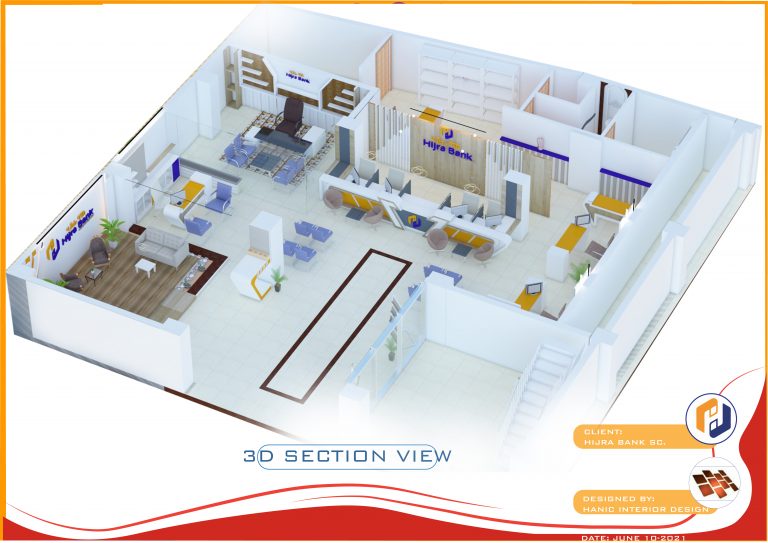
The pipeline below exists to get the geometry and the discipline of the BIM model into the rendering environment without dragging in the chaos. We use it on every interior visualisation in the studio, from a single apartment to the Hijra Bank competition set, and it has survived enough deadlines to be worth writing down.
The core principle: the Revit model is the single source of truth for geometry, and 3ds Max owns nothing but materials, lighting and camera. Any time you model in Max something that should have come from Revit, you have created a second truth, and it will diverge the first time the client moves a wall.
Stage 1 — Model discipline in Revit
Ninety per cent of a painful export is caused by decisions made weeks earlier in the model. Fix these and the handover takes minutes.
Name materials for the renderer, not for the drawing
Every Revit material becomes a material ID in Max. If forty walls all use Default Wall, you will spend an evening selecting faces by hand. Create distinct materials for anything that will read differently in the render — INT_Paint_V2_Matt, INT_Timber_Oak_Vertical, INT_Stone_Honed_Floor — even when the drawing set does not care about the difference.
Keep families clean
Replace heavy manufacturer families with simplified geometry. A downloaded chair family with 400,000 polygons and a full parametric fabric system will destroy your viewport and contribute nothing to the render, where it will be replaced by a proper 3D model anyway. Use placeholder boxes at the correct dimensions and swap them in Max.
Use a dedicated export view
Create a 3D view called 3D_EXPORT. In it: hide annotation, hide levels and grids, hide furniture you intend to replace, turn off any section box you do not want, and set the detail level to Fine only for the elements that need it. Never export from the working view — you will export somebody's temporary section box and not notice until the render is halfway done.
Fix the units and the origin
Set project units to millimetres. Note the position of the internal origin and use shared coordinates consistently. If the model sits 40 km from the origin because it was linked to a survey, move a copy back before export — large coordinate values cause z-fighting and precision artefacts in Max that look like flickering surfaces in the render.
Stage 2 — The FBX handover
FBX is the workhorse. It carries geometry, material IDs, cameras and basic mapping, and every version of Max reads it.
- Open
3D_EXPORT. Check the view once more for stray elements. - File → Export → CAD Formats → FBX.
- Tick “Use level of detail” off, and leave “Without boundary edges” unticked unless you have a specific reason.
- Export to a project folder that will be the Max project folder — not to the desktop. Relative asset paths save you later.
- In Max, use File → Import, not Merge, and choose Add and update animation, Units: Automatic, and untick Cameras unless you want the Revit cameras.
Check the scale immediately
The first thing you do after import — before anything else — is draw a box 1000 mm tall next to a door. If the door is not roughly 2.1 boxes, your units are wrong. Fixing scale after you have placed lights and cameras costs an afternoon.
When to use Datasmith or a live link instead
If the project is heading for real-time (a client walkthrough in a game engine rather than stills), a live link is worth the setup because geometry updates propagate. For still images and short animations, FBX is faster, more predictable and does not tie you to a plugin version.
Stage 3 — Cleanup in 3ds Max
An imported Revit model is technically correct and practically hostile. Twenty minutes of cleanup pays for itself many times over.
- Attach and group by material. Revit exports each element separately. Select by material ID and attach into logical objects: all walls, all floors, all glazing. Fewer objects means a faster viewport and a manageable scene explorer.
- Reset XForm and collapse on anything that came in with a strange pivot or negative scale, or your modifiers will behave unpredictably.
- Delete what the camera never sees. The back half of the building, the floors above, the ceiling in a floor-level camera shot. Every polygon you delete is render time you get back.
- Fix the normals. Imported geometry frequently has flipped faces that render black. Apply a Normal modifier with Unify, or use the Edit Normals tool on the offending faces.
- Add UVW mapping. Revit's UVs are inconsistent. Apply a UVW Map (Box, real-world scale) to each attached object and set the tile size in millimetres so that a 600 × 600 mm tile actually measures 600 mm in the render.
- Replace the placeholders. Swap the box furniture for proper models, snap them to the floor, and check nothing intersects a wall.
Stage 4 — Materials that behave physically
Use a physically based workflow throughout. Whatever renderer you use, the principles are the same, and mixing legacy and PBR materials in one scene is the fastest route to an image that looks subtly wrong and cannot be fixed by grading.
| Surface | Roughness | Notes |
|---|---|---|
| Matt emulsion paint | 0.6–0.8 | Never pure white. Use RGB 230–240 maximum or it blows out. |
| Satin lacquer joinery | 0.25–0.35 | Add a subtle bump; perfectly flat lacquer reads as plastic. |
| Honed stone | 0.35–0.5 | Large-scale variation map is essential; repeating stone is the classic tell. |
| Polished porcelain | 0.05–0.15 | Add a light smear/roughness map — real floors are never uniformly polished. |
| Timber floor | 0.3–0.45 | Vary roughness plank to plank with a noise map. |
| Glass | 0.0–0.05 | Thin-walled for single panes; give it a faint green tint and a hint of dirt. |
| Fabric | 0.75–0.95 | Needs a real normal or displacement map plus a sheen layer. |
| Brushed metal | 0.2–0.4 anisotropic | Set the anisotropy direction to follow the brushing. |
Three habits separate convincing materials from flat ones: every material gets a roughness variation map, even a subtle noise; nothing is pure black or pure white; and real-world texture scale is checked against a human figure before the first render.
Stage 5 — Lighting the scene
Light the render the way you would light the room. If the design has cove lighting, put cove lighting in the scene — not an invisible area light floating in the middle, which is the standard shortcut and the reason so many renders look like showroom photographs rather than rooms.
Daylight
Start with a physical sun and sky at the real latitude and the hour the room is most used. For Addis Ababa the sun is high and the light is hard; a shallow sun angle from a European default will make the whole image feel foreign. Add a portal or dome light at each window opening to help the sampler.
Artificial
Model the real fittings with real photometric values. If the schedule says 650 lm at 2700 K with a 36° beam, build exactly that. When you later change a fitting in the schedule, the render tells you honestly what happens.
Exposure
Set the physical camera to a sensible photographic exposure — ISO 200, f/5.6, and adjust shutter — rather than pushing light intensities until it looks right. A physically sane exposure means the daylight and artificial layers can be balanced by changing lamps, which is what a real lighting designer would do.
Stage 6 — Camera and composition
- Lens. 24–35 mm equivalent for interiors. Anything wider distorts furniture and makes rooms look like corridors; anything longer will not fit the space.
- Height. 1.4–1.6 m for standing views, 1.1 m for seated spaces such as lounges and restaurants. Never the default 1.0 m, which makes ceilings loom.
- Keep verticals vertical. Tilt the camera and every wall converges. Use a two-point perspective correction — it is what an architectural photographer does with a shift lens, and its absence is instantly readable.
- Compose for the design, not for the room. Ask what one decision this image exists to explain, and frame that. A view that shows everything explains nothing.
- Set the render resolution early and compose to it. Reframing a 4K image after approval means re-rendering.
The pre-render checklist
Run this before every overnight render. It is boring and it has saved us hundreds of hours.
- Scale verified against a 1000 mm reference box and a human figure.
- No black or white materials; all diffuse values between RGB 20 and 240.
- Texture real-world scale checked on floor, tile and fabric.
- All geometry has UVW mapping; no default checker visible anywhere.
- Normals unified; no black faces in the viewport.
- Lights match the lighting schedule in lumens and colour temperature.
- Camera vertical, lens 24–35 mm, height correct for the use.
- Render output path set, file naming includes a version number.
- Render elements enabled for post: reflection, specular, AO, Z-depth, object ID.
- A low-resolution test render reviewed at 25 per cent before the final launches.
Always save render elements
Z-depth, ambient occlusion and object ID passes cost almost nothing to generate and let you fix in ten minutes what would otherwise be a four-hour re-render. If the client says “can the floor be a little warmer”, an object ID mask answers that in Photoshop.
Stage 7 — Post-production, and when to stop
Post-production should correct, not rescue. If the render needs saving in Photoshop, fix it in the scene instead — you will need the scene again for the next four views.
A reasonable post pass, in order: exposure and white balance, a gentle curve for contrast, selective warmth using the object ID masks, a light bloom on the brightest sources, chromatic aberration and vignette at very low strength, and finally a small amount of grain. Grain is the most underrated step; a perfectly clean image reads as computer-generated to almost everyone, and two per cent of noise reads as photography.
Stop when the image communicates the design. A visualisation is a decision-making tool for the client, not a portfolio piece for the artist — and the client is not paying for the extra six hours nobody will notice. Our 3D visualisation service is built around exactly this pipeline, and the Revit and 3ds Max courses teach it step by step.
Written by the studio
Hailegebriel Girma is part of the Hanic Interiors design team in Addis Ababa. If this article raised a question about your own project, write to us — we answer every message within one working day.